
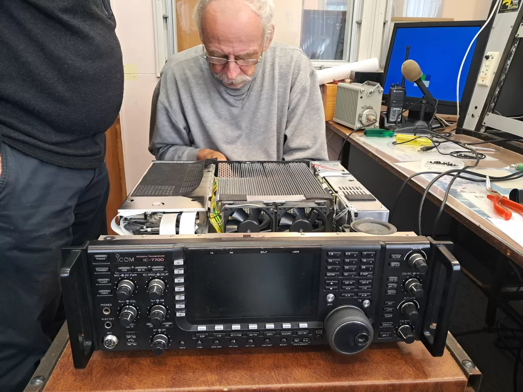
Quite unusually, we were sitting around the kitchen table having a coffee, and in wandered [redacted]. “The 7700’s not transmitting”. Oh dear – coffee interruptus. Indeed, after checking the obvious, there wasn’t a hint of RF output. Well, the upside was we were looking for a challenge (not).
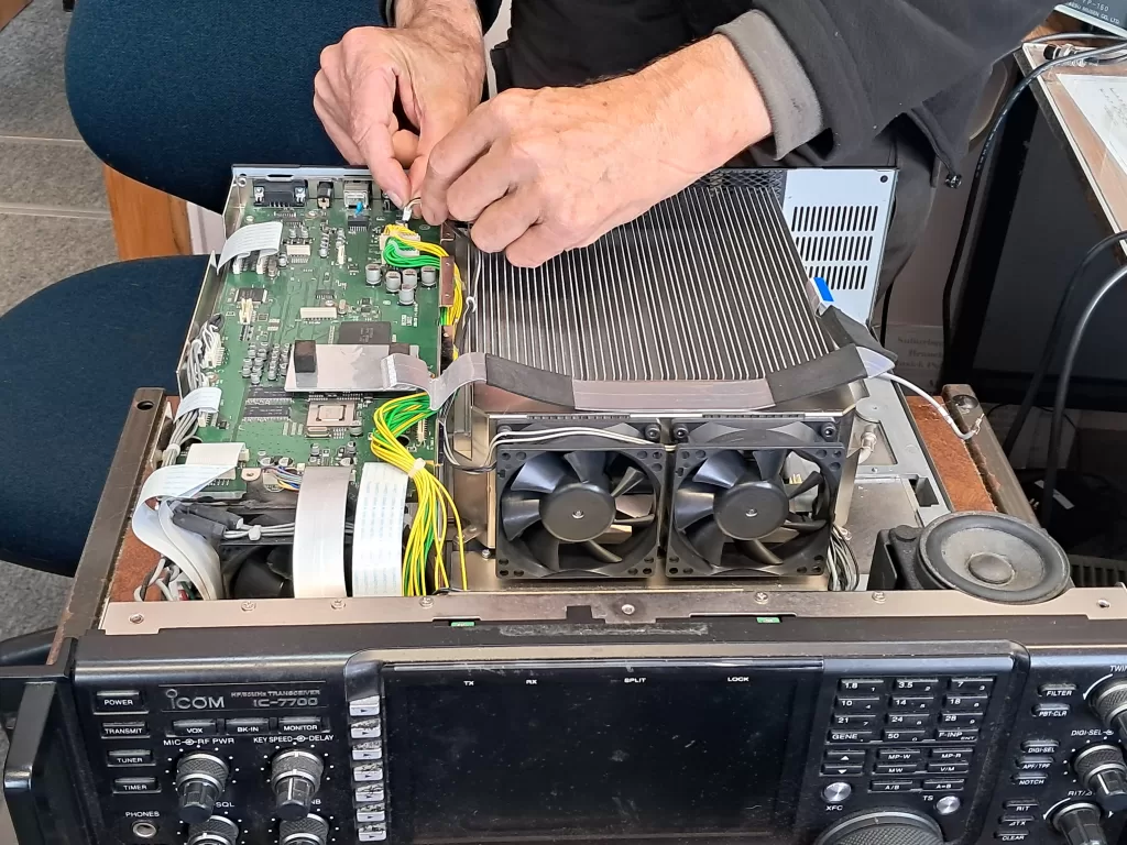
So out of the rack it came ( a two person job ) and we sat it down and removed some covers. Now sometimes, when you get to work on a piece of equipment that the designer obviously prioritised the concept of serviceability of, you almost fizz with excitement. The idea that everything you need to access is easily reached and is assembled in a way that you can simply and intuitively disassemble is every service persons dream. Unfortunately, the 7700 is not one of those designs.
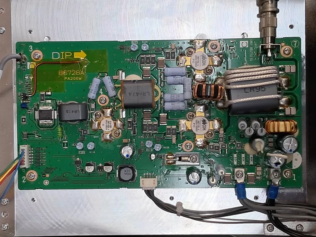
Initial symptoms were no TX RF out on any band. Idling current for the P.A. stage appeared reasonable with an indicated 2.5A compared with 3A given in the alignment instructions. This suggested that the output and driver devices were hopefully OK. Now 3A @50v = 150W idling dissipation; little wonder the P.A stage is hidden under a heatsink that looks like a porcupine on steroids. After a while, we had intermittent but unstable RF out – hopefully this would assist in tracking down the fault.
The driver PCB was easily accessible, so we started there. However, we soon came to the conclusion we needed to work on the PA module. The upside is that the PA PCB is relatively sparsely populated. The downside is that it can’t bee seen until the complete PA assembly is removed and from the chassis and inverted. That should be a simple job, but it looks like the P.A module was mounted in the centre of the chassis, then every other part added on afterwards. There were screws and plugs that couldn’t be accessed until we removed the antenna tuner module on one side and the controller module on the other. Eventually we had the P.A. module PCB side up and we could get to work.
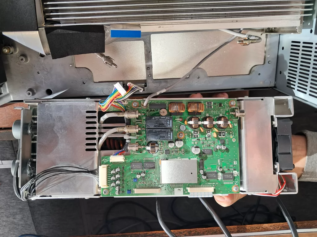
Strangely, when you invert a module, some of the “just long enough” cables won’t reach the connectors that are no longer where they should be. Still, the power supply and control signals did reach and we directly attached a dummy load power meter, so that was supposedly enough to continue.
We started by checking the drive to the PA stage. The drive signal was clean and stable, but intermittently it cut off – and the 7700 would lock up. After each reset, the drive would cut off after an ever decreasing period. Considering this could be related to temperature, we turned off the 7700 and went off for a coffee. On returning to a now cooler 7700, we confirmed the cutting off was related to temperature. Now one of the cables that couldn’t be connected when the PA stage was inverted, was the fan power. Musing that the processor might monitor the fan current draw ( the fans are only 2 wire devices), an extension cable for the fans was required. The connectors were JST types and “how convenient” Dave ZL1DL just happened to have connectors and crimp tool in his waggon. 2mm crimp contacts weren’t designed with “old eyes” in mind and it took an inordinate amount of time to construct a 4 way extension cable ( yes they are two wire fans and there are two of them! ). Cable in place, fans operating and now the drive remained on. So the issue is on the PA module.
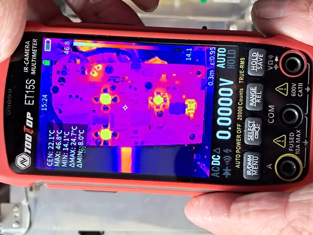
Harry produced an IR camera so we could see the hot devices when the transmitter was enabled. The PA unit has two stages of amplification followed by the driver then the finals. The mosfets in all four stages displayed a rapid temperature rise on key down. We took some reference voltages, then conveniently experienced a failure of RF out. Another view with the IR camera showed the first amplification stage to be cold. Voltage measurements confirmed it was not working.
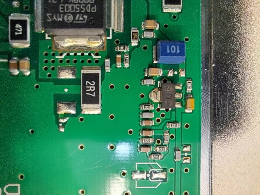
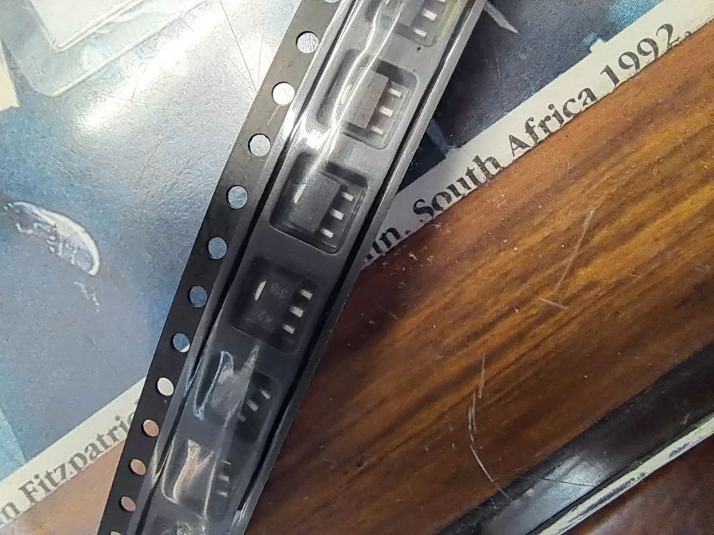
The repair went on hold while Dave sourced a replacement for the pre-amplifier mosfet. Keith, ZL1BQE brought his “hot tweezers” over and Harry did the deed and replaced the device. We powered up and were greeted with full and stable power output.
A quick survey with the IR camera showed the pre-amp running at over 100°C. We had no reference temp , but all agreed it probably wasn’t ideal. The mosfet is in a SOT-89 package and the large tab on one side extends under the device, for contact to the PCB for heat dissipation. We reflowed the soldering of the tab to ensure the under side was soldered to the PCB. This didn’t result in any significant temperature decrease, so we decided to improve the heatsinking by the addition of a “heatpipe” to the tab of the device.
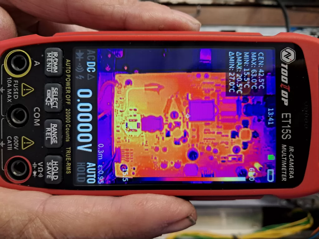
With the heatpipe in place the pre-amp device stabilised at around 85°C – better than 15°C lower than without the additional sinking. Still much higher than I would like, but within the operating spec for the device. We ran the power up to more than 150w ( limit of the power meter we had connected ) and there was still plenty in reserve – the 7700 is 200w capable. Importantly the power output was stable. So nothing for it, but to reassemble all the removed parts and refit the case – and at the end we managed to find homes for all the screws that were previously removed!
A big thanks to Harry and Keith for their input in the repair of our #1 (modern) transceiver!