
There’s no question that “switching” converter technology has revolutionised the way we construct and use power supplies. From cost and weight saving compared to low frequency transformer designs, to efficiency and performance in voltage or current regulation, the switching regulator is almost the holy grail in power supplies. Apart from noise that is. Noise that the majority of users are blissfully unaware of; but Hams know what we are talking about. The RF noise that comes about from the efficiency of fast switching circuitry. Not necessarily a deal breaker – just another challenge.
A common design in switching converters is the DC to DC converter. Very conveniently, it can provide a regulated desired voltage sourced from a different voltage. Either the source voltage may be higher than the output voltage ( buck converter ) or the source voltage may be lower than the output voltage ( boost converter ). Typically, there is a minimum differential voltage required for the converters to operate – this can be in the 1 ~ 4 volt region. So a buck converter for a 10v output could need a minimum of 14v supply to operate. There are situations where this minimum difference in voltage can not be accomodated. So enter the buck / boost converter [BBC].
As it’s name implies, the buck / boost converter can provide a given output voltage from an input voltage in a range that is from below to above the desired output voltage. There is no minimum input to output differential voltage requirement – the input range is seamless. This bodes well for managing voltage from battery supplies.
Historically, Ham rigs have been constructed to operate from a notional 13.8v source – nominally the voltage from a fully charged lead acid battery. However, for convenience, Hams are adopting lithium based batteries and these tend to have differing voltages. Take for example, Li-ion technology. A Li-ion cell can have a nominal voltage of 3.7v, with a maximum charge voltage of 4.2v and a low voltage cutoff of 2.8v. If you construct a battery with 3 series [3S] cells, the voltage can range from 12.6v down to the low voltage cutoff of 8.4v. For a 4 series [4S] cell battery, the voltage could range from 16.8v down to 11.2v. Neither of these scenarios are particularly useful for powering rigs that are expecting near to 13.8v.
So a buck / boost converter is just what we need. Regardless of battery voltage variation, it will deliver a level 13.8v or whatever we set it to. And noise, don’t forget the noise. All we need to do is get rid of the noise.
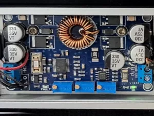
Harry ZL1BK, embarked on such a quest. His G90 go case has a [4S] battery pack that was manually managed for voltage by switching in “dropper” diodes as required. When he installed a BBC to automate the voltage regulation, additional noise in the receiver was quite evident. The BBC was supplied as a PCB, so a “U” channel of aluminium was used to mount and partially shield the board. A section of PCB material formed a 4th side to the shield. Still the noise persisted. The input and output wires were then bifilarly ( if that wasn’t a word previously, it is now ) wound around toroids, but the noise steadfastly remained. Frequency suitable bypass caps also failed to silence the pesky noise.
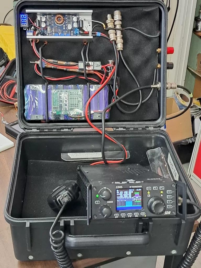
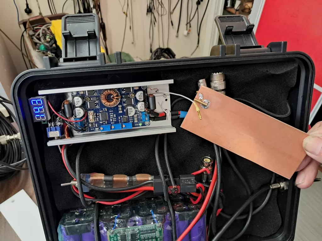
In a show of brute force, Harry put around a dozen turns of a single conductor through a couple of binocular ferrites1 and achieved a very high attenuation at his desired 40m band. With chokes in place ( at the input and output of the BBC ), there is now no discernible noise from the BBC affecting the G90 receiver. Well done Harry!
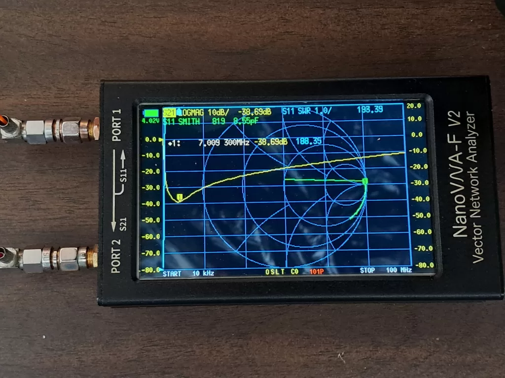
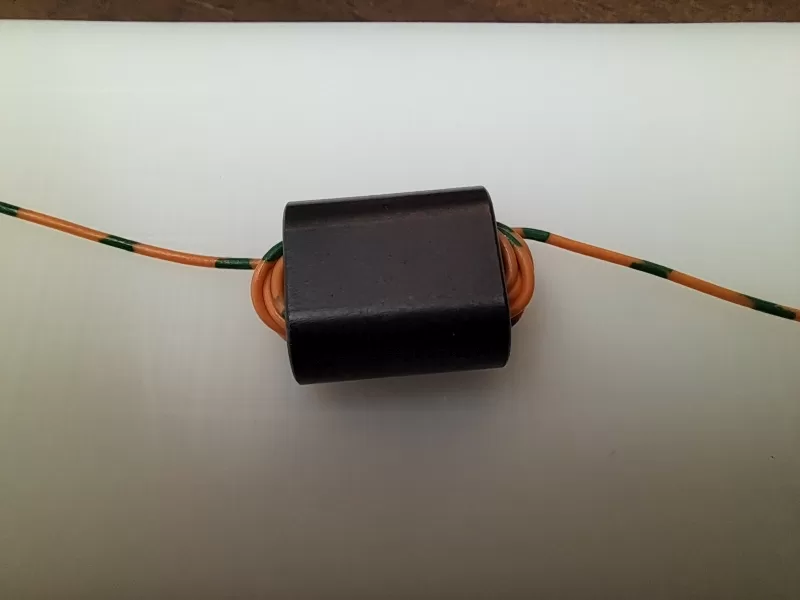
- Wires carrying significant current ( as in power supply connections ) should be wound in a bifilar manner through a ferrite to provide differential cancelation of the magnetising effects of the power supply current. Otherwise the high value of Ampere-Turns may cause flux saturation of the core and therefore not allow maximum EMI blocking. The large number of turns increases the attenuation impedance but at the cost of bandwidth ( the additional capacitance added by the close wound turns also lowers the frequency of the attenuation band ). In this case the target 7MHz was achieved by adjusting the number of turns. ↩︎