
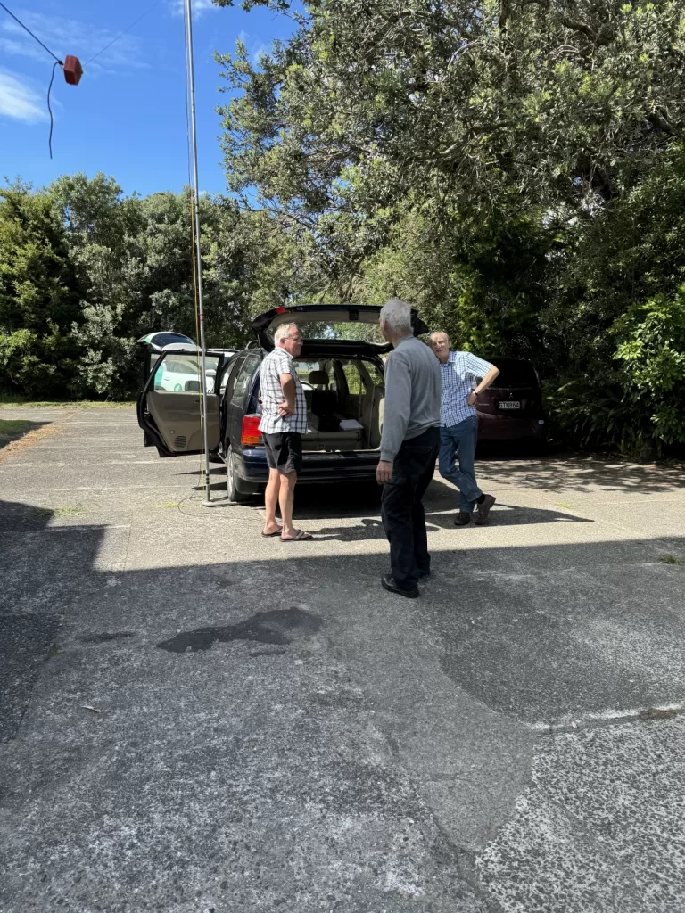
The day started out with an impromptu fox hunt. Harry, ZL1BK, hid a nano-VNA that was sweeping a narrow range around a 2M freq. More of a proof of concept than a serious hunt, it did highlight the need for directional antennas to be able to easily get a bearing on the signal. We were using HT’s and only had relative signal strength to go on. The resulting discussion on a compact directional antenna left people considering the possibility of using a small loop. We’ll see what turns up!
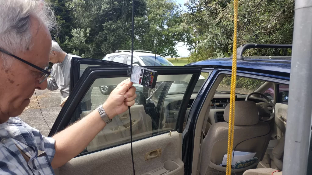
We then moved on to HF antenna testing. When impedance transformation is not required, is a balun actually necessary at an antenna feedpoint? Todays exercise compared current detected on the outside of the braid on a feedline for two types of 1:1 balun and a direct feedline connection with no balun. RF Current on the outside of braid is known as common mode (CM) current and is undesirable, as it represents current that should have resulted in radiation leaving the antenna, but didn’t. A mismatch of the antenna feedpoint impedance to the feedline results in CM current. A balun might reduce the CM current and force more current to result in radiation.
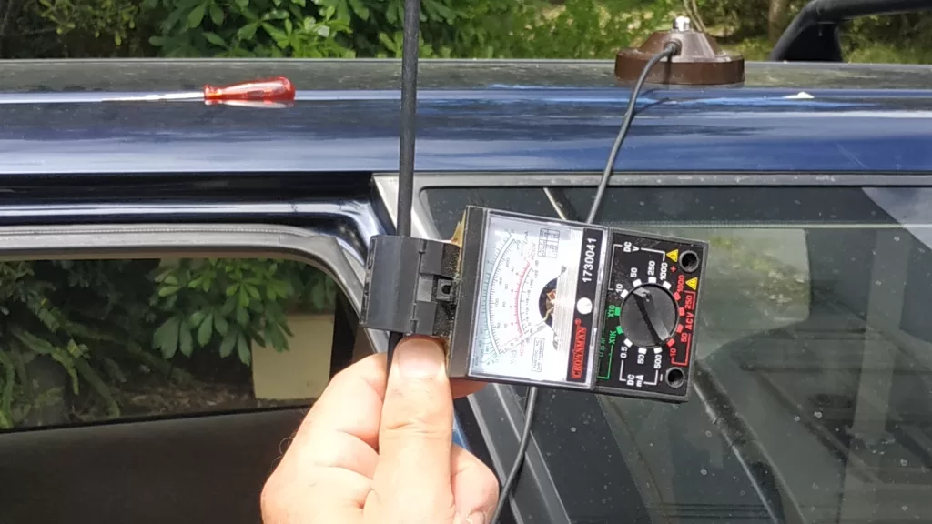
RF current can be monitored with a ferrite core around the current carrying wire. The wire forms the primary winding of a transformer. Several turns of another wire around the core form a secondary. The output of the secondary is rectified and fed to a meter movement. The “BK-1” antenna current meter (ACM) was built by Harry, ZL1BK, and uses a “Split Core” ferrite for easy attachment to the cable under test and a small multimeter for a display. The multimeter is considerably cheaper and easier than buying a box, meter movement, and potentiometer for sensitivity setting and then having to assemble said items.
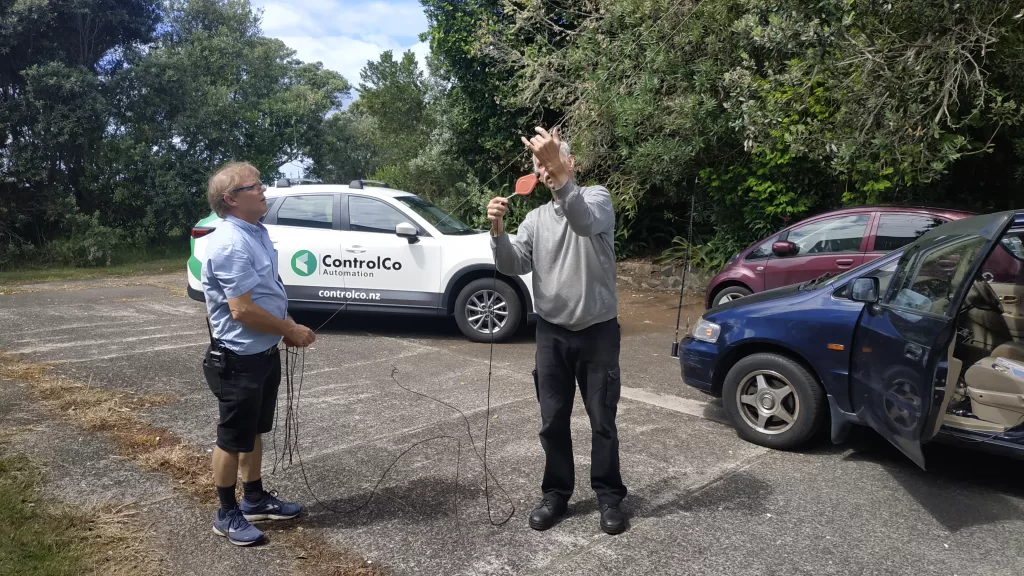
If an antenna is not a perfect match to the feedline, some imbalance current will occur. With a wire dipole, there are several contributors to a mismatch, including feedpoint impedance not being 50 ohms; owing to antenna height above ground, angle of wires etc. and reactance caused by antenna componentry and proximity of buildings, trees etc. (That was two etc.’s in one sentence – note to self to find new author…)

So what did we find out? On a relative basis, both baluns ( a ferrite based current choke and a trifilar wound voltage type ) reduced indicated current on the outside of the feedline braid by a factor of around 5 over the value indicated on the directly fed configuration. So the baluns appear to be effective in reducing CM current. Another effect of employing a balun is to improve a potentially distorted radiation pattern. No attempt was made to evaluate any variation in such pattern, although it is reasonable to assume that an effect of reducing the CM current would be to improve the radiation pattern. After such deep musings, we retired to the tearoom for a coffee and some of Luke’s Nan’s delicious date and walnut loaf…