
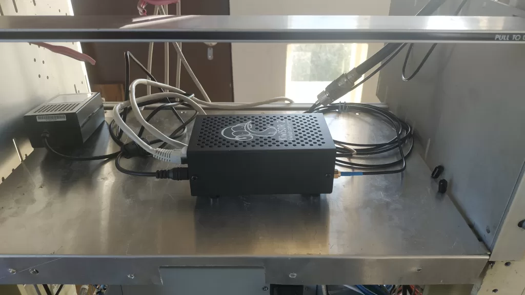
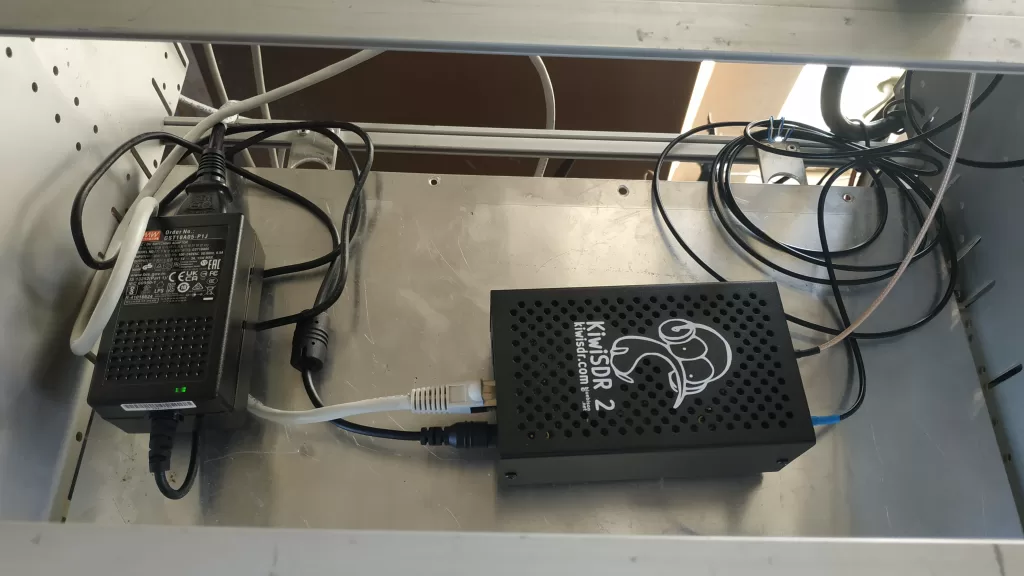
Spam, Spam, Spam, Spam ( with apologies to Monty Python ); The Spam Group ( Society for the Preservation of Amplitude Modulation ) has invested in a brand new Version 2 Kiwi SDR. With no permanent location yet sorted for its installation, we are hosting it at MP.
Now one of the issues we face is a lack of surplus antennas. The ideal antenna for a full HF receiver would be a flat response type located at a distance from the clubrooms. Alas, all we had spare to hand was a 40 / 80m trap dipole set up as an inverted Vee over the tower, extending across to the two side decks. But it worked. There are very obvious “noise peaks” on 40 and 80, but the antenna provides useful reception through to 30 MHz.
A bigger problem is, all of the low band antennas are at, or close to, the clubrooms, and therefore transmitting on one antenna might just induce significant RF levels into other nearby antennas. And so it likely was. The Kiwi suddenly became deaf. A few AM broadcast stations at very attenuated levels were all that were being displayed.
The KiwiSDR forums were a great help; a number of KiwSDRs of the latest design had gone deaf – presumably from a little too much signal into the antenna connection. Now the relatively new version 2 of the Kiwi has the addition of a programmable attenuator at the front end of the receiver. It appears that this part (not surprisingly given its location) might succumb to too much signal. Indeed, tests in switching the attenuator levels confirmed it wasn’t behaving as it should do. The forums suggested that one could jumper over the failed attenuator to restore hearing. Great! A ten minute repair. Not…
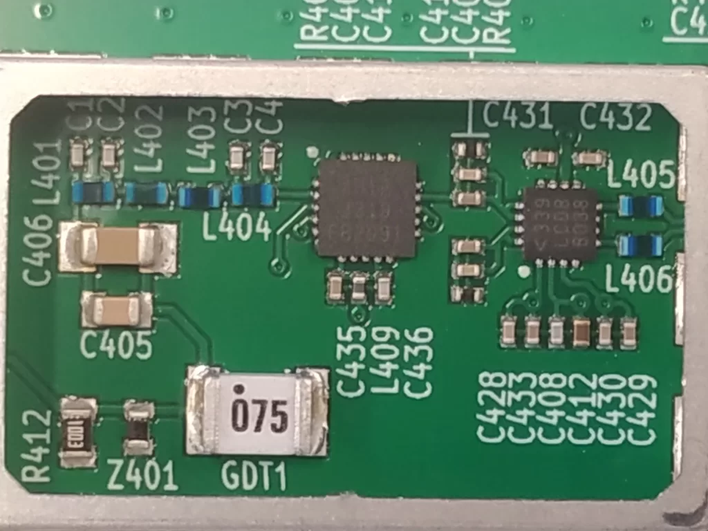
The attenuator is a QFN package – contacts around the 4 edges, but effectively on the underside. The 20 “pin” package is around 4mm x 4mm and lead pitch is 0.5mm. Even through the pads are slightly proud of the attenuator package – I’m not going there. The components connecting to the input and output of the attenuator were not much easier: with a size that is smaller than tiny, soldering a jumper on to one end wasn’t for me.
A request for help to the KiwiSDR email received a reply within an hour! “Send it to us and we’ll see what we can do”. So off it went, and within a few days it was returned working! Always buy local 😀
In the meantime, we set about measuring the RF level that a local transmitter could induce into the receive antenna. Then we also constructed a front end protection (FEP) unit to divert high power away from the Kiwi.
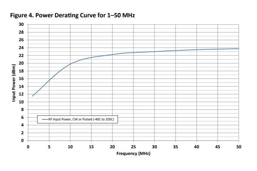
The attenuator in the Kiwi is rated at an absolute maximum input power of 1 watt (30dBm). However, there is a derating curve for HF (the attenuator is good for 4 GHz) for recommended operation that suggests at 80m, the maximum input power should be 25mW (14dBm) and “Operation between operating range maximum and absolute maximum for extended periods may reduce reliability”. So our protection needs to ensure less than 25mW of RF gets into the Kiwi.
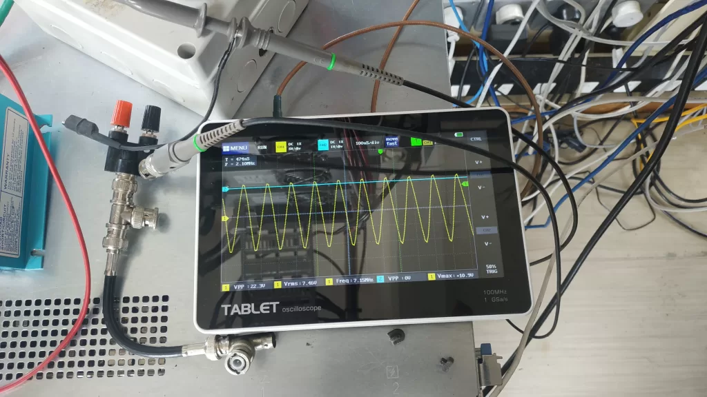
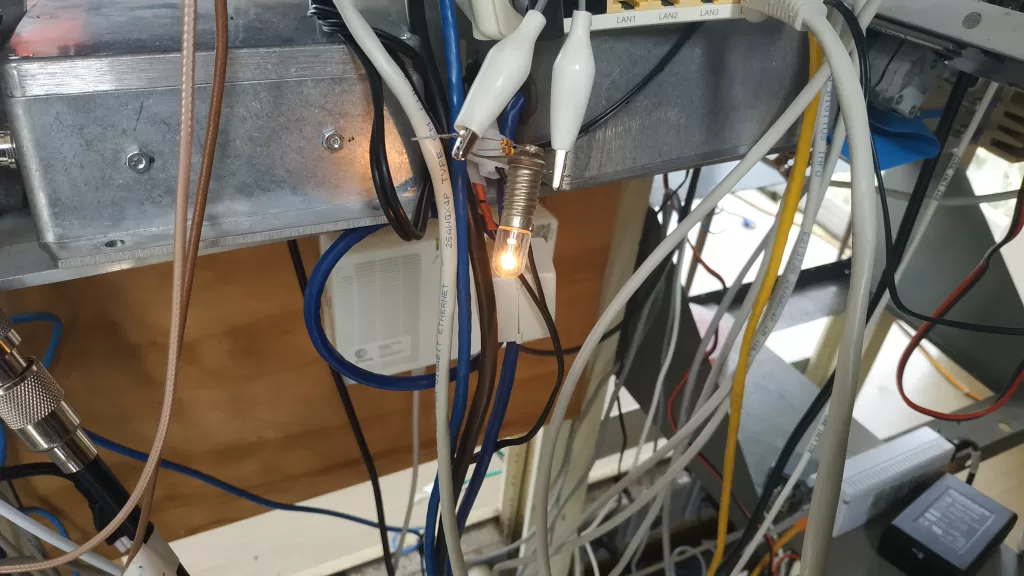
We initially attached a 12v lightbulb to the receive antenna and applied the torture test. The highest amount of induced RF came from the nearby 40m 3 wire dipole when force fed by an approximately 900w of carrier… This resulted in a very bright lightbulb that rapidly turned black on the inside of the glass. Substituting a 50 ohm terminated power meter, gave us a reading of around 23 volts that is ~ 11watts. Slightly above the target 25mW… So we not only need to clamp the maximum voltage that is presented to the Kiwi, but potentially dissipate a reasonable amount of power. Clamping the output voltage is easily achieved with diodes, but we couldn’t ask them to deal with all the power. Now one can lower the induced power level by raising the impedance presented to the antenna when higher levels of RF occur. This complicated sounding arrangement is easily provided for with an incandescent lamp! When the filament is cold, the resistance is low. When the filament heats (from an elevated RF level), the filament resistance increases. How convenient.
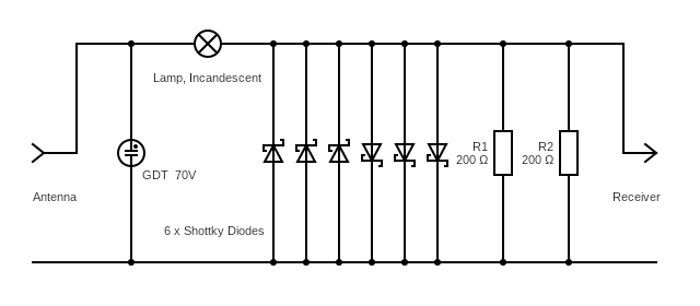
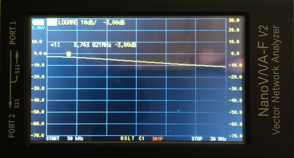
The circuit for the first iteration of FEP is shown above. A Gas Discharge Tube acts to limit any high voltage spikes, and the resistance to ground stops any static build-up. Multiple diodes were incorporated to guard against an (unlikely) open circuit failure. There is a significant increase in input to output attenuation with increasing frequency. This is potentially mainly from the diode capacitance, and will be looked at in the next iteration of FEP. Tests show the maximum output when 900w is being transmitted locally, to be less than 2mW ( 2dBm ) passed to the output. So the SDR should be protected for now. Further development of the FEP will be towards an improvement in flattening the frequency response and lowering the low signal attenuation, while maintaining a reliably limited output.
The SPAM KiwiSDR is available HERE