
T98 T-R Relay Box update Graham ZL1TOF 2024-01-18
The Collier & Beale T98 transmitter was modified in 2020 to run on 40 metres. As it was a beacon and was always on with no provision for intermittent operation. The relay box was built to provide remote operation from the console with aerial change-over from receive to transmit and back as required by the operator. The original design did not do the job.
With a large capacitor across the relay coil a large surge current flowed through the console key-switch The key-switch was designed with telephones in mind, so without a data-sheet, a good guess would be 20 mA and 50 V. The rectified and unfiltered 24 volts would be about 83% of the required 24 volts for the relays. With the 2200 uF capacitor 30 volts would be applied to both relays. The relay coil heats up with the 1.5 Watts being dissipated (2.4 W @ 30 V). The temperature rise is added to the ambient inside the T98. There is usually a spec for maximum operating temperature, and perhaps a derating curve for contact rating and life. No data-sheets are available for new old stock and junk box parts.
What do we want it to do? We want the aerial to be switched over to the transmitter before the HT is switched on. And we want the HT to be switched off before the aerial is switched to the receiver.
What to do about it? First, regulate the rectified and filtered supply to 24 volts. Then make a sequencer like used with amateur microwave setups to drive the relays. More modern designs tend to use a microcontroller1 which can have all the delays adjustable with a dumb terminal connection. Other designs use logic gates2 and RC timing networks and opamps3&4. I chose the simple RC network and a couple of voltage comparators to detect the voltages and thus delays to operate the relays.
I designed the circuit using a circuit simulator and made sure there was no bad behaviour at power up and power down. The rest was simple, fiddle a few values to get the times we want with the parts available. It can’t be worse than it was.
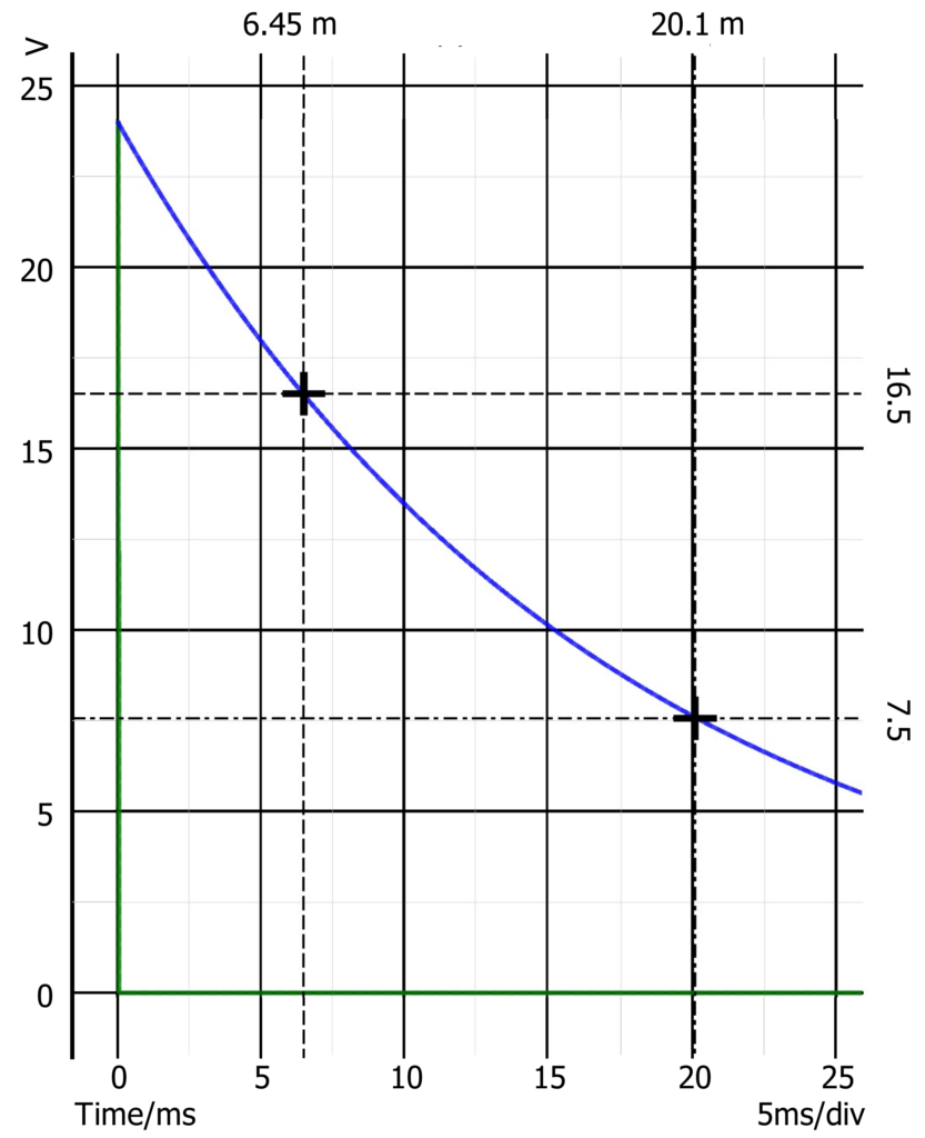
Referring to the circuit, R1 applies voltage to the key switch and limits the current to 12 mA when the key switch is closed for transmitting. R1 consists of 2x 1k0 ¼ W resistors in series derated to 60% power dissipation. The RC network is R2, R3 & C5. The diode, D5, changes the time constant, shorter for receive to transmit and longer for transmit to receive. U2A is a voltage comparator. When the negative (-) input is at a higher voltage then the positive (+) input, the output is active low, keeping the transistor turned off and the relay not energised. The voltage divider R4 & R5 gives a voltage of 16.5 volts for the first delay period. The other comparator, U2B, works the same except the positive input is at 7.5 volts. When switching from receive to transmit U2B operates later than U2A. Using this RC time constant formula we get:
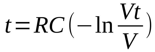
Where R = 36 k ohms (150 k parallel with 47k),
C = 470 nF V = 24 volts &
Vt = 16.5 volts (7.5 volts), so,
t = 6.34 ms (19.7 ms),
but, C has a 10% tolerance and so have the delays
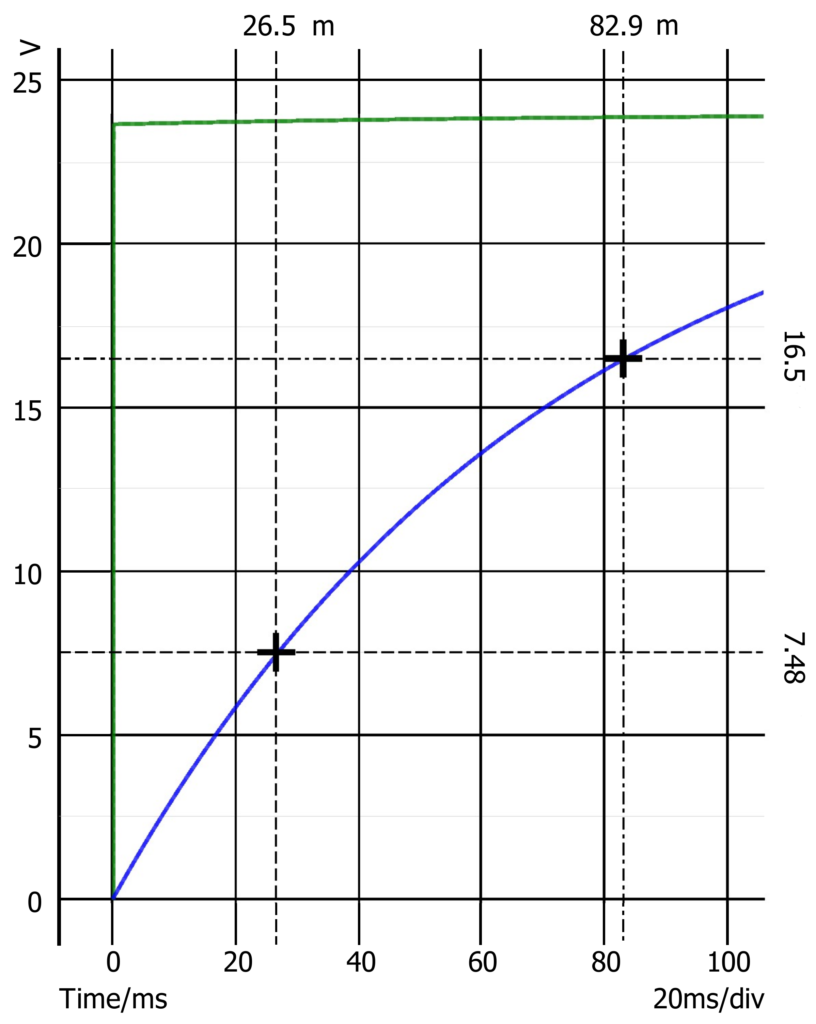
When switching from transmit to receive, U2B operates before U2A. Using the other RC time constant formula we get:
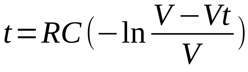
Where R = 152 k ohms, C = 470 nF, V = 24 volts & Vt = 7.5 volts (16.5 volts), so, t = 27 ms (83 ms), as before the delays have 10% tolerance.
The output of the comparator is open collector. The bias for the relay driver transistor is also the pull-up. Aim for 100 mA for the relays. The BC337-25 data-sheet has the minimum gain of 160. Using the rule of thumb “5 times over drive for saturation” means we need Ib = 5*100/160 = 3.125 mA. The rule of thumb for base-emitter on voltage is 0.8 volts. Then R6 & R9 = (24-0.8) / 0.003125 = 7k4, so use 6k8. Measured saturation Vc-e should be under 100 mV. The comparator can sink 6 mA, so that will be OK.
A circuit diagram was drawn in Kicad. There are 3 sections to the schematic: the circuit board; the internals of the relay box; and the connections into the T98 circuit.
The PCB was made on 0.1 inch (2.54 mm) pitch strip board (Vero Precision Engineering Ltd made strip-board from about 1960). I had to make the PCB fit the space and use the existing holes. I used the regulator as one mounting point and a spacer at the diagonal corner. The spacer was made from a 6 mm length of 5 mm copper coated steel tube. I soldered the spacer to the strip board to make assembly and service, if needed, easier.
I use the template, pencil and eraser method to design the strip board. I found this good page on the internet about how to make a stripboard https://www.bestsoldering.com/how-to-use-veroboard/ .. When the design is complete I cut the board along the holes and clean up with a file. I use a 3 mm twist drill in a pin chuck to create the cuts in the tracks.
This design has 10 wires connected to the board. Two go to the large electrolytic capacitor. The remaining eight need to be disconnected if the board is to be removed. I used new old stock PCB pins that were once used in a black and white TV circuit board. They had single sockets crimped to the wires fitted to them. The terminals press into the PCB holes and are very firm. I could have used 0.1” pin header and a socket, but, that would have made the PCB harder to design.

Before the board was fitted to the case it was tested. In 2 stages, first when the power supply and regulator were fitted. Then when all the components were soldered in. Measure the voltage and see the signal travels through the circuit from the key switch input to the relay outputs. I soldered the wires on after the PCB was fitted to the case.
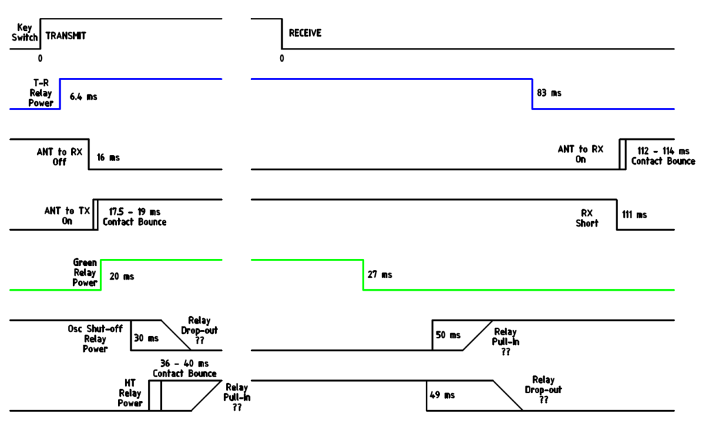
The timing diagram shows the measured timing relationship between the various parts of the circuit and agrees well with the calculations. The receive to transmit delays are shorter than the transmit to receive. This is to allow for the faster relay operate and slower dropout times. There is an HT switch on the receiver. If the operator timing is wrong feedback can occur, and the receiver can take several seconds to recover from the strong local signal. It is proposed that the 40 metre receiver will have a mute on transmit with provision for netting.
1. ‘The “At Last!” Radio TR Sequencer’, VE2ZAZ, QST March 2007
2. ‘Digital T-R Control Sequencer’, K7AYP, VHF Communications 1/2009
3. ‘DEM LTRS Transmit / Receive Sequencer’, Down East Microwave Inc
4. ‘4 Event Sequencer’, W6PQL, Internet.