
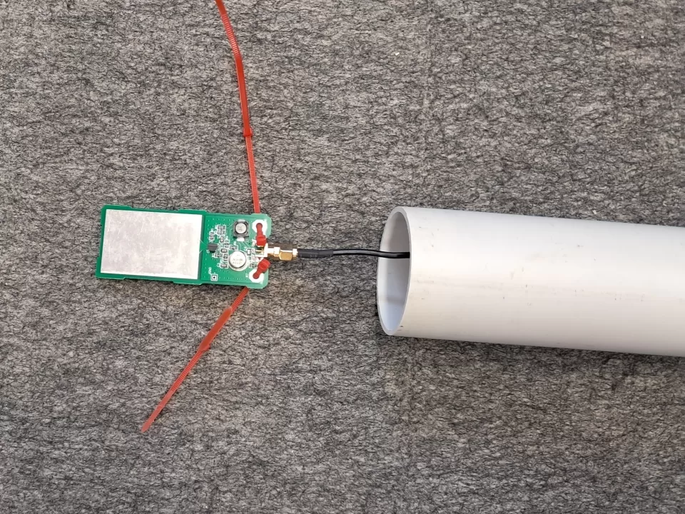
An HF antenna that has a physical capture area of around 60mm x 40mm? Yeah right. The SDRs at MP need an antenna that is some distance away from the building, to escape both intense RF fields from transmission antennas around the structure, and other QRM from the vast range of digital noise producing equipment inside. Given the difficulty in placing new HF antennas, we decided to go small, and a patch antenna might do the trick.
While we have a reasonably remote site in mind, for initial testing the antenna is mounted on the top of the building – with the acceptance there will be some noise from nearby tech. The testing is to see whether we might achieve acceptable reception with such a small antenna.
A patch antenna (also constructed in a very short rod form, known as a mini-whip), works on the basis that although the antenna is very small, and the received signal is also very low level, the received noise is also very low and in fact the signal to noise ratio is comparable to a much larger antenna. The antenna presents a VERY high impedance at HF and so a FET is used directly at the antenna connection to present a high input impedance at the first stage of the local amplifier. Following the FET stage, an emitter follower provides a low impedance (50 ohm) output to the coax.
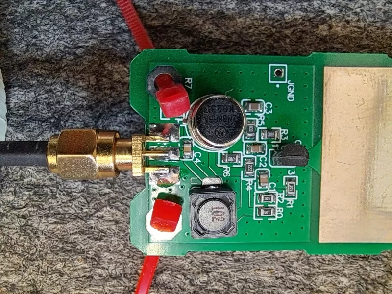
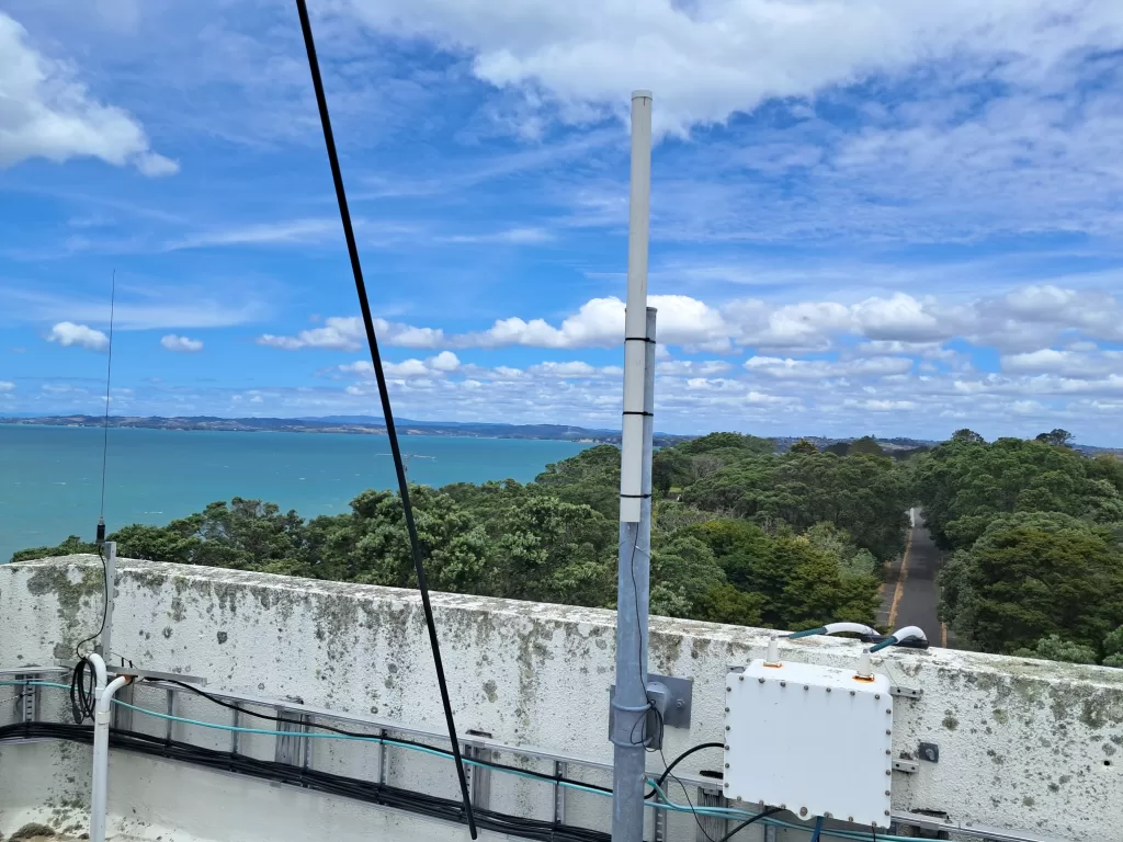
The antenna assembly was temporarily installed on a support on the tower. It was then patched into an existing coax run to the repeater level rack, where the SDRs are installed. At the rack end of the coax, a DC injector was fitted and a 9v battery attached to power the antenna amplifier. It was hoped the battery would last at least a day, to provide for some testing at different times.
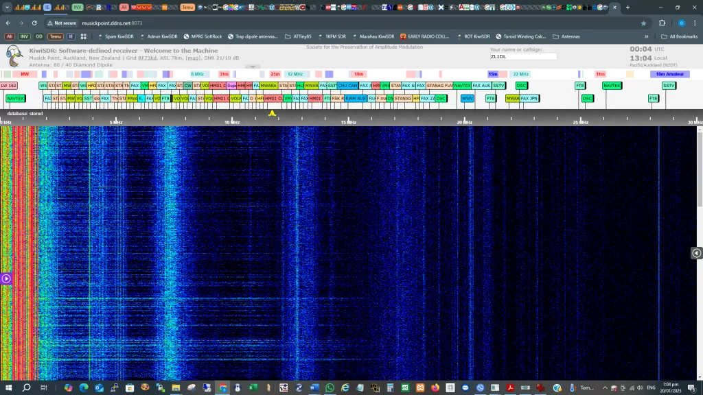
The patch antenna worked reasonably well, although the noise level appeared elevated. When the battery went flat, the SDR still displayed signals which we decided was due to the coax braid not being earthed.
22/1/25 – Repatched !
Based on initial observations, today we arranged earthing for the feedline, at the rack end. This had some benefit as far as noise went, and removed the signals that were being received on the coax. The interesting time came when we added in a power supply instead of the battery. The first plugpack we tried resulted in substantial Intermodulation Distortion (IMD). Another plugpack had terrible switchmode noise present on the spectrum display. A 12v linear supply ( actually 14v ) was tried and resulted it massive IMD. Puzzled, we then tried a variable supply ( the amplifier for the patch antenna is designed to operate with a supply range of 9 to 14 volts. It became evident the IMD increased significantly with supply voltage increase. At higher than 9v, the strong AM broadcast stations created significant IMD products – visible on the waterfall display as horizontal lines. At 9v, the IMD was evident but minimal, but at 12V and above it was overwhelming.
We fitted a BCI filter – highpass above 2MHz. This substantially reduced the AM Broadcast signals, and the IMD stopped. The BCI filter was borrowed from, and had to be returned to, the IC-706 remote HF. So we trialled fixed attenuators; 6dB seemed a reasonable tradeoff to limit the IMD at a 12v supply voltage. That was the configuration that was left for further evaluation, as it was coffee time!
To be continued: The reason for the IMD needs to be determined. The patch amplifier has approximately unity gain, so the sensitivity to IMD at different supply voltages is puzzling. It could be inherent instability in the amplifier design; indeed others have proposed different designs with lower IMD. The braid of the coax feedline to the antenna forms a significant part of the antenna; we have around 8m of vertical height of coax ( a substantial part of which is indoors and therefore susceptible to QRM ). We will try improving the power supply bypassing at the antenna amplifier, and installing a choke on the coax at a point that is external to the building to “terminate” the receiving section of the coax and hopefully reduce the QRM that currently is picked up on the indoors section of the coax. Filters to remove the strong AM BC signals and signals above 30MHz are also a consideration. Another day, anther coffee…