
Today, we had couple of noise related projects. Firstly, the Man in the Box is back from his extended holiday. Yes the 5775 repeater is now back to its unique identity with the voice announcements, EOT beep and long tail. Noise that is Musick to our ears [ stop trying to be funny – ed ]. It’s not easy being different…
Then, with the impending install of a KiwiSDR, we went looking for a low noise power supply for such. With a general agreement that an “old fashioned” linear regulator type supply was likely the quietest, we had a problem in not having a 5v 3A supply of such type to hand.
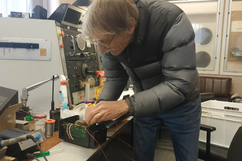
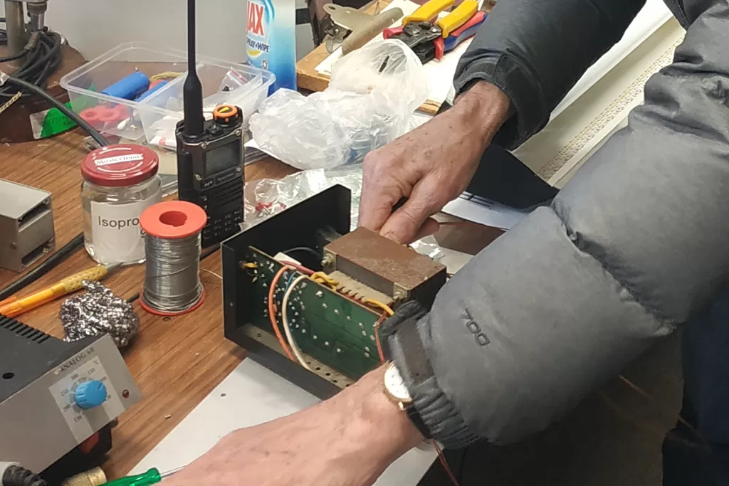
We found a 12v linear supply that looked like a candidate for conversion to 5v. Of course, asking the regulator circuit to dissipate an extra 7v to get the output down to 5v, was a bridge too far [ hold the rectifier jokes please – ed ]. So dropping the transformer output voltage is the required. Fortunately, the transformer sports a split bobbin ( primary and secondary windings are separated sided by side ). To change the output voltage, we need to determine the voltage per winding turn of the secondary winding. There was sufficient space in the transformer to insert several test turns and make the measurement. Now, armed with the results of the test measurement and the actual voltage the transformer outputs to provide the power supply 12V DC output, we can remove the required turns to make the transformer suitable for a 5v supply. Potentially, [ the jokes need to stop NOW -ed ] there may be room to add a new winding and not disturb the existing.
John, ZL1OJ has been working to tame his newly installed non-resonant endfed HF antenna. Like many suburban locations, noise is a major headache at John’s place. As part of noise reducing trials, we made a feedline choke for John to trial. Inserting such part way along the coax feedline could potentially lower the receive noise and protect against transmit RF returning to the rig, however on transmit a puzzling instability ensued. Described as a horrendous and unstable increase in SWR, we thought the choke may have failed. Given the choke construction is simply multiple turns of coax on a ferrite core, there isn’t too much to go wrong. So John brought the choke back to the club, and we tested it out and found it to be fine.
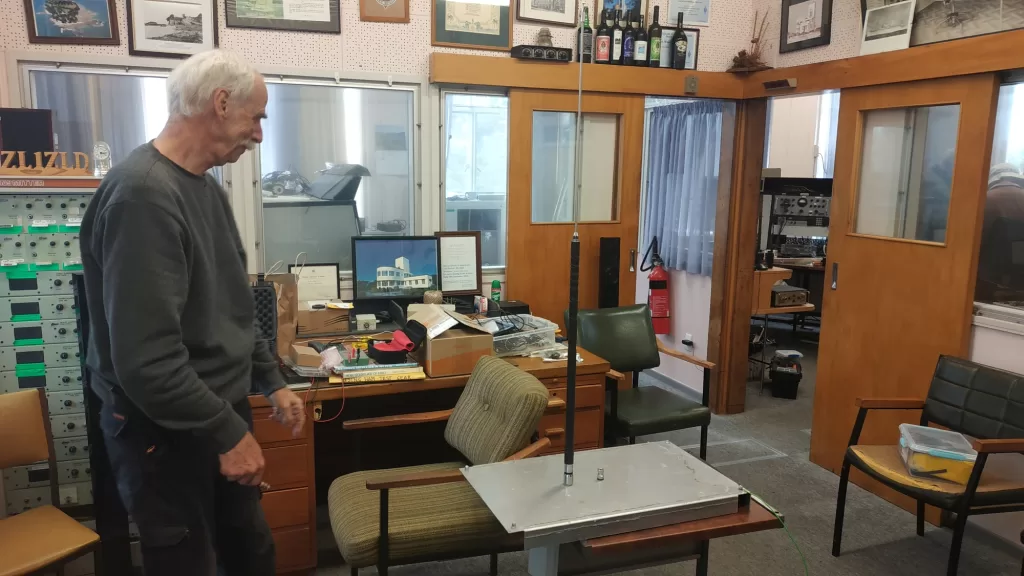
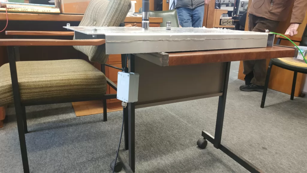
We set up a test vertical on 80m and connected a nano vna via a 6m cable. Without the choke in place, the nano display was noticeably changed by touching the coax connection near the nano. With the choke in place, the nano was undisturbed by touching said connector.
Now the astute of the readership will note that the “groundplane” that the vertical is mounted on is quite small for a 3.5MHz antenna. Consequently, the test cable braid adds considerably to the antenna mass. This is clearly illustrated in the pics below, that shows the antenna resonant point moving higher when the choke is installed – effectively removing the cable as part of the antenna.
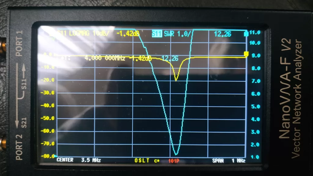
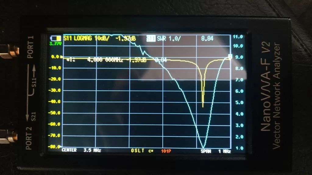
Also, despite the small mass of the “groundplane”, choking off the cable results in a better return loss! Regardless, adding the choke was a good demonstration of how easily a feedline can become part of an antenna – with the potential to deliver noise and RF power to the transceiver.
So why did adding a choke to John’s feedline result in the massive SWR indication? I believe indication is the keyword. The choke is unlikely to have caused a massive SWR change. The indication may result from an increase in RF returning to the rig – the opposite of what should happen when a choke is utilised!
The coax from the antenna feedpoint, at around 2m above ground, goes to the ground level, across to the house then rises up the side of the house to the second floor. The choke is inserted at ground level, partway along the coax. The vertical rise is relatively parallel to and not far from a vertical part of the antenna. It might be that the coax segment from the choke to the rig is having transmit power coupled to the outside of the braid, by virtue of the coax running parallel to the antenna and being elevated. With the choke in line creating a high impedance point on the coax outer, the induced RF will be encouraged to be delivered to the rig! If the choke were to be moved to a point on the second floor just before the coax enters the building, it may halt pickup from entering the building. Indeed there are some recommendations that 2 chokes are installed – one at a point to set a terminal length for the braid contribution as an antenna element and a second one at the entry to a house to stop RF noise from entering the house. Usually, the coax downstream of a choke is perpendicular to or trailing away from the antenna. In this case, having the coax parallel and close to the antenna may be resulting in the opposite to normal desired behaviour for a choked feedline! TBC…