
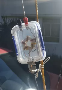
John ZL1OJ has put up a commercial non-resonant endfed HF antenna. The antenna, approximately 20m in length promises to cover ham bands from 80 through 6 meters. An endfed wire will typically have a feed impedance somewhere between 400 and 600 ohms for frequencies where it does not resonate. A resonant endfed wire may have an impedance in the low ohms ( 10 ~ 70 ) for antennas that are odd multiples of a 1/4 wave, or very high impedance ( 2,500 to 4,000 ohms) for lengths that are multiples of a half wave. So if we can select a wire length that is not resonant on any bands of interest to us, we will have a relatively small range of feed impedances on all of those bands. This range of impedances ( 400 ~ 600 ohms ) can be transformed by a 9:1 unun to a relatively close range around 50 ohms. Such is the simple theory.
The length of the main radiator for a non-resonant antenna is quite easily chosen to not be resonant on bands of interest, however endfed antennas do not work effectively as a single wire; they do need a secondary path, commonly know as a counterpoise, to handle the differential antenna current. While this “counterpoise” does not need to be of the same magnitude as the main element, it will contribute to the antenna and therefore affect the frequencies at which the antenna resonates. If no counterpoise is explicitly provided, the antenna current will use the coax braid ( feedline ) as a path for imbalanced antenna current ( the current that really would like an antenna element to flow on, but there isn’t one). Even if a counterpoise is added to the antenna, there will be a division of current between the counterpoise and braid in inverse proportion to the impedance of the two paths. If the braid imbalance current is not stopped, it can travel back to the transceiver and interfere with the transceiver operation and even provide RF burns to the operator. One way to allow part of the coax braid to be used an an antenna component while stopping unwanted RF current reaching the transceiver, is to place an RF choke at a point on the coax. The choke is designed to only work against the current flow on the outside of the braid; normal transmitted power that utilises the center conductor and inner side of the braid is unaffected.
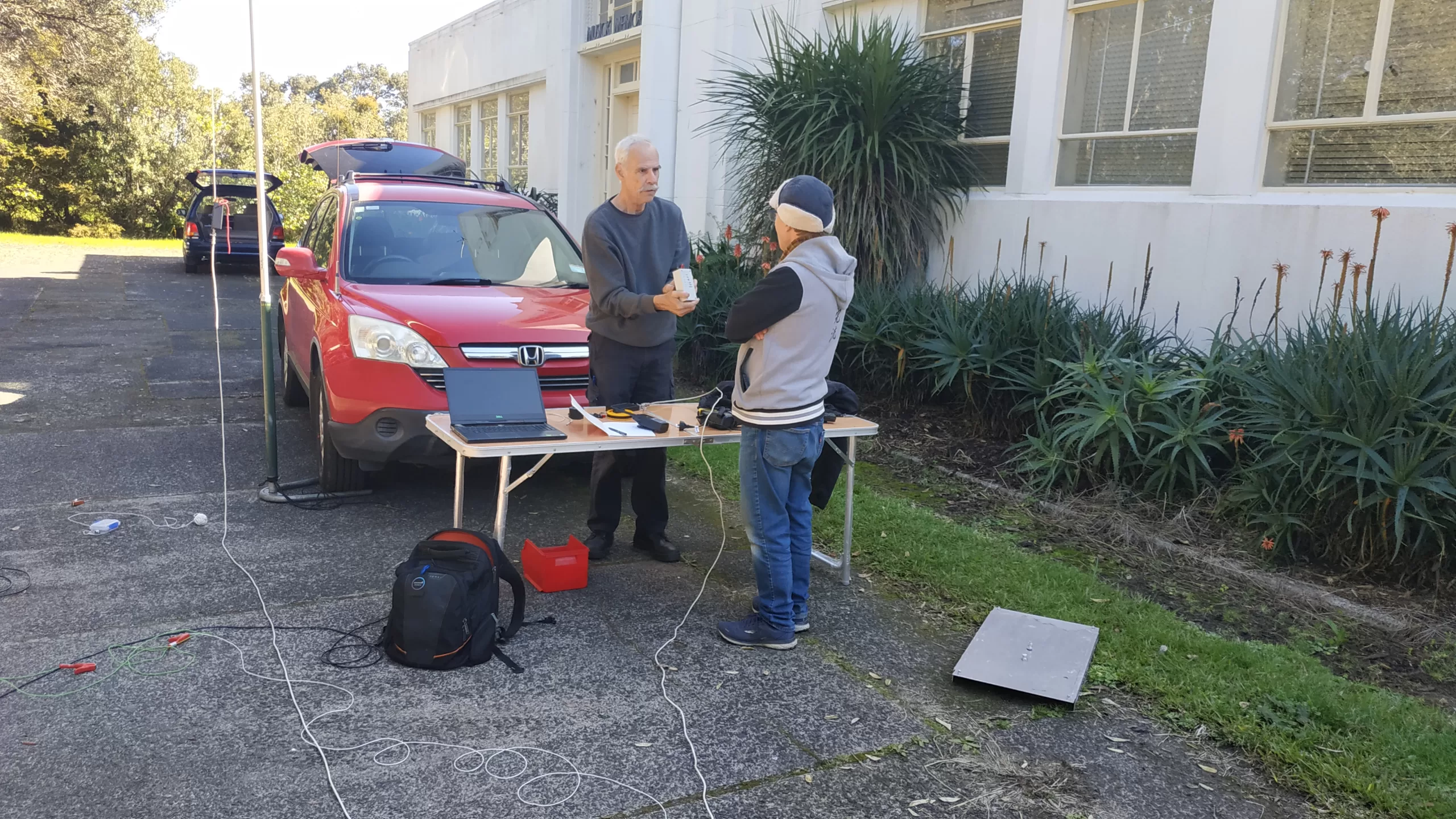
However, when John added a choke midstream on his coax feedline ( in the interests of reducing received noise – another use for chokes ), an extremely high SWR resulted, making transmission impossible. How could this be? Potentially, the choke has shortened the effective braid length contributing to the antenna and a resonance on or near the frequency in use has resulted. To test this theory, the investigative committee of Dave ZL1DL, Harry ZL1BK and Rob ZL4ROB constructed an endfed antenna approximating the design that John had installed. The tests were interesting.
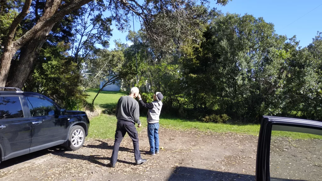
The test antenna consisted of a 20m wire rising to 6m AGL on a pole support from a 9:1 unun at around 2m AGL. The wire then continued horizontally to a handy tree.
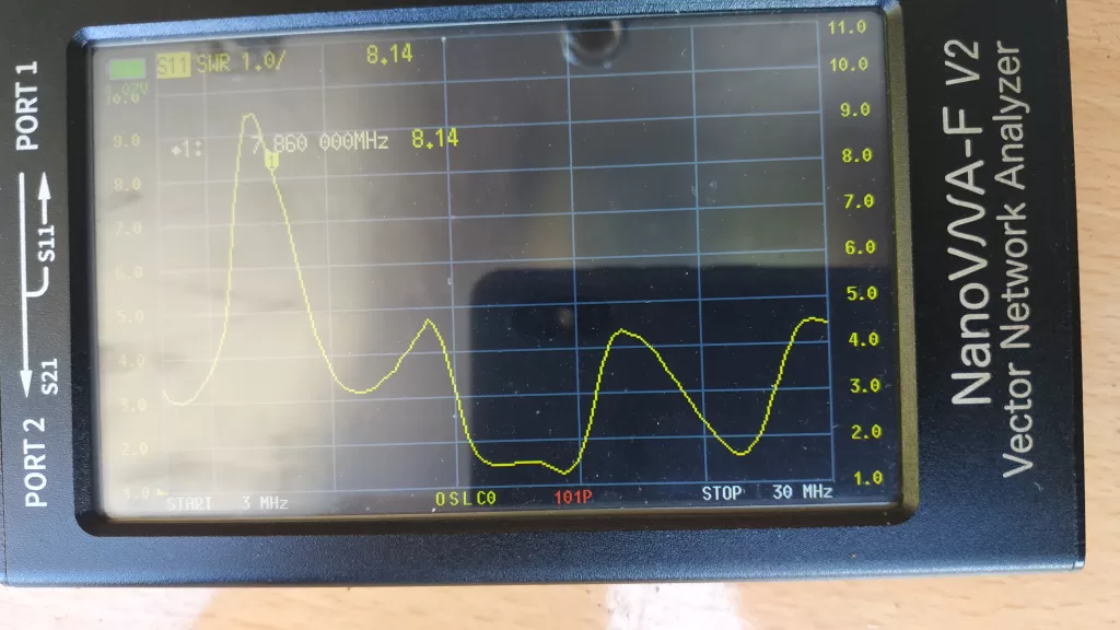
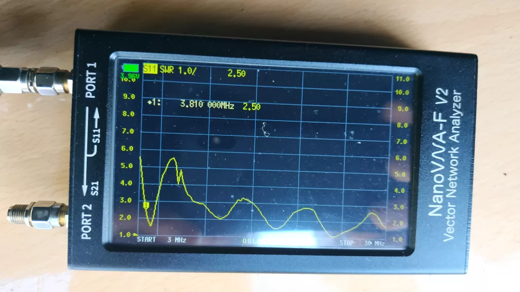
Initially, a 6m length of coax from the unun to the nano vna was the only counterpoise. Touching the connector on the VNA changed the response considerably, illustrating the sensitivity of the counterpoise.
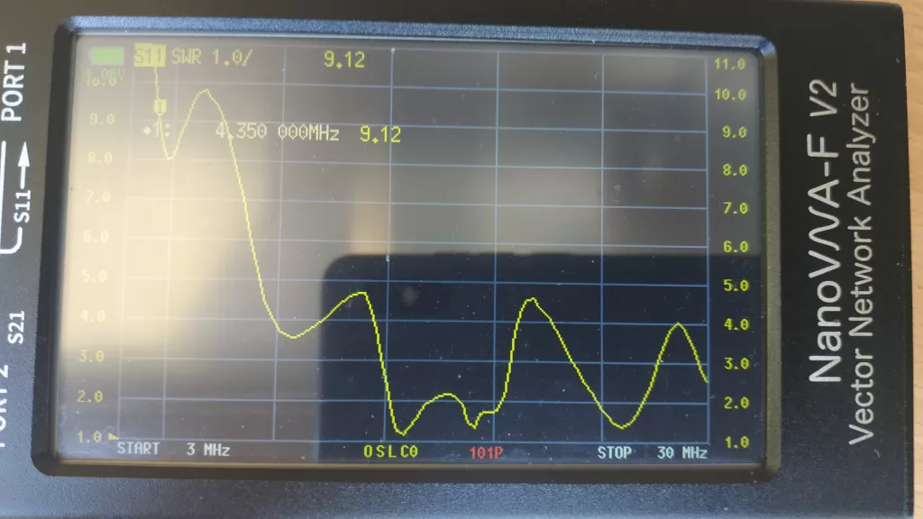
Apologies for the photo quality of the nano display. These were taken outside on a bright sunny Auckland winter’s day!
Various combinations of coax length with and without an “earth” connection ( either laid on ground or connected to a driven stake ) were trialed. The results displayed considerable sensitivity especially at the low HF frequencies to variations in the “counterpoise”.
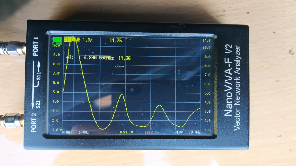
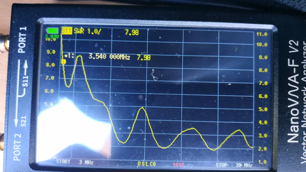
The 80m response was improved considerably by providing an earth connection from the unun to a 300mm long stake ( not a substantial RF earth connection but quite effective ).
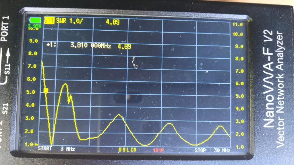
Extending the coax length to 20m has improved the SWR figures with an unexplained sharp dip around the first peak ( pic 4).
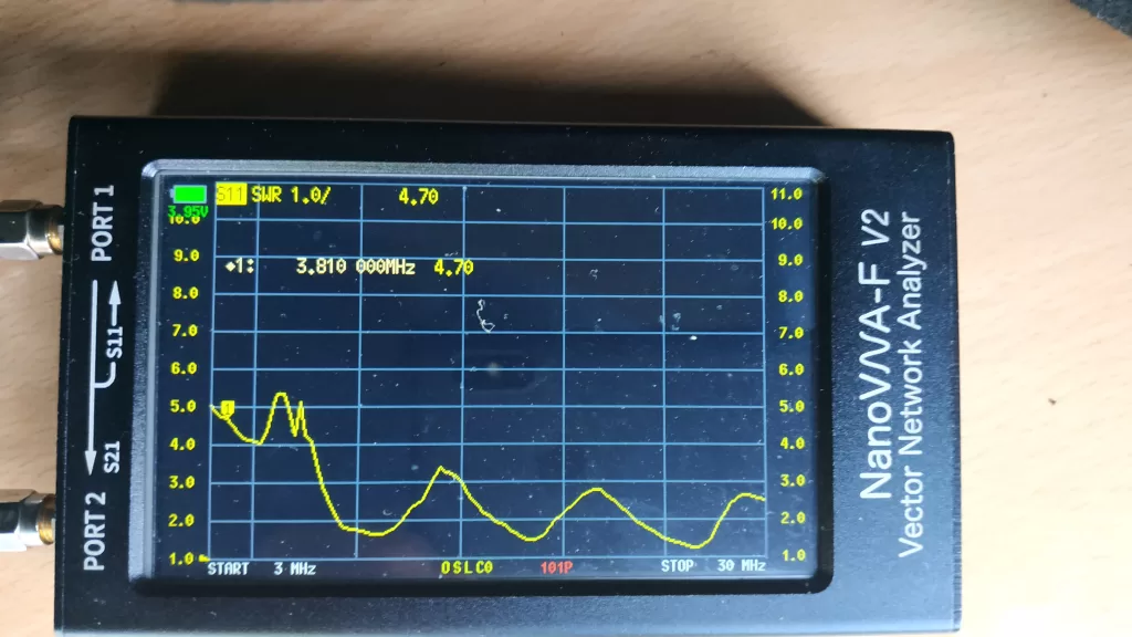
The ground wire was reconnected to the unun ( pics 5 & 6 )
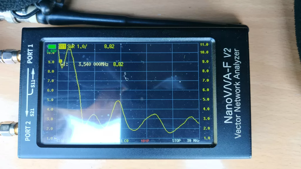
Our experiment showed that adjustment of the non-resonant antenna to accomodate lower frequencies was somewhat difficult and unpredictable. The best gains were made by utilising a longer coaxial cable and connecting the unun to an earth spike. To be continued…