
MiniLink – A Computer to Radio Interface for Digital Modes
AREC have adopted Winlink (an email type messaging system) as a preferred text-based communication platform. Winlink can utilise radio as an interconnection medium and so is well suited for Amateur adoption. A PC along with a connected transceiver provides a client workstation.
Many transceivers, especially hand held devices, do not have inbuilt interfaces to connect to a PC, and accordingly, an external device is needed to provide the required functionality. While there are a number of interfaces available, Dave ZL1DL suggested a physically small unit with minimal componentry ( to minimise power consumption ) for portable use, would possibly be an interesting club construction project. Keith, ZL1BQE has recent experience in interface development ( how convenient! ), and has eagerly applied his alibities in the development. While the MiniLink was inspired for use in a portable WinLink workstation, it is not specific to WinLink and should be useful for other digital modes as well.
At its simplest, audio (both RX and TX) needs to pass between the radio and computer and a PTT control from the computer goes to the radio. While it is possible to utilise the sound card that its integral to computers, critical adjustment of the microphone and speaker level is required for best data throughput. Adjustments to suit other computer applications might change the optimal settings for data, so a separate soundcard is included in the interface. This soundcard is dedicated to the Radio data only and so the onboard audio levels will not need to be changed for the MiniLink. The soundcard LSI chip also contains several GPIO pins – one of which is utilised to provide the PTT signal.
The initial concept was for a matchbox sized interface containing a USB interface for audio A/D, D/A and PTT control, with permanently attached cables for USB and radio. Galvanic isolation between input and output was not considered necessary in a hand-held radio / laptop configuration as ground loops were quite unlikely. While the matchbox size interface was entirely possible, it would require mainly surface mount components. Given this was being developed as a club assembly project, it was decided the SMD solution was not ideal for constructors without SMD soldering experience. To remove the need for soldering the LSI chip, a PCB from a USB sound card is used directly as part of the MiniLink componentry.
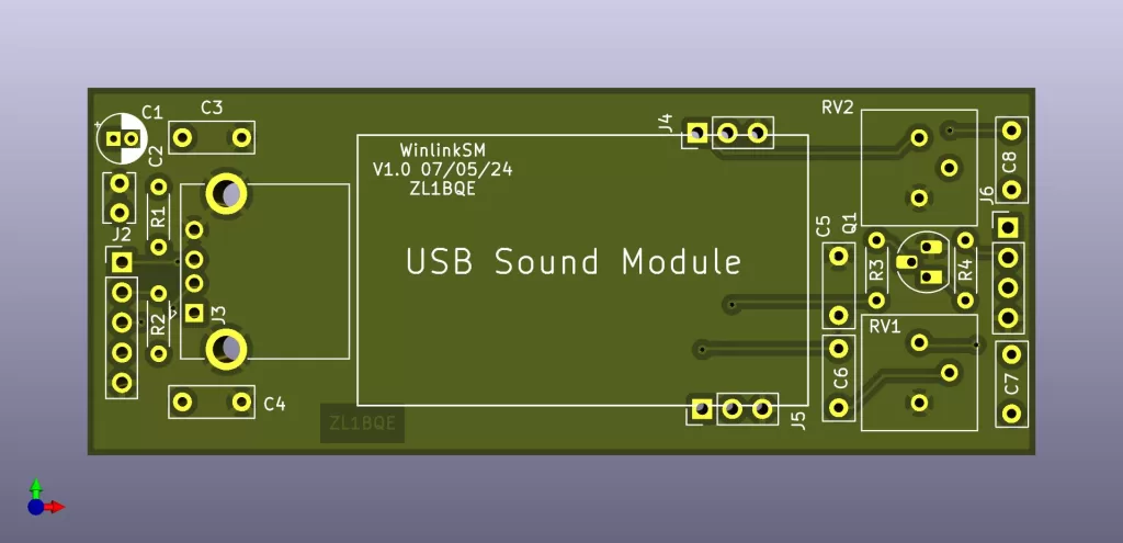
Version 1
Development version 1 was a single PCB in a housing 35 x 26 x 80mm. It was considered desirable to have sockets for the USB and Radio connections, but there was no room on the PCB for the sockets and clearance for panel mounted connectors was insufficient. Accordingly, the USB and Radio cables would need to be permanently attached, through grommets on the end panels.

That aside, a test build PCB highlighted an interesting problem of audio shaping. When the interface was utilised with a test radio set up for data TX/RX, max WinLink throughput speeds were achieved. When the interface was used with a hand held radio, the RX data achieved speed was around 20% of maximum. It was considered that the poor performance could be as a result of de-emphasis (audio shaping ) in the hand held radio.
With voice or broadcast FM transmissions, to achieve a higher audio signal to noise ratio, it is usual to boost the higher audio frequencies (pre-emphasis) before transmission and then apply an equivalent high frequency reduction (de-emphasis) to the received audio. In radios configured for data transmission, both TX and RX audio emphasis are usually disabled.
In the case of the handheld radio; it was providing de-emphasis to the received audio, that had been transmitted with a flat audio response from a data configured radio. The de-emphasised audio was impacting the received data rate. Back to the drawing board.