
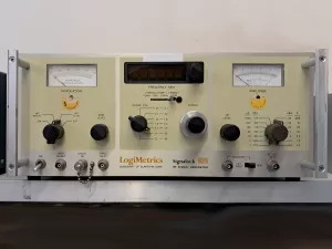
For some time, one of the RF generators in the workshop has been a little off colour. Notably, the leading digit on the frequency display was not working and modulation was raspy.
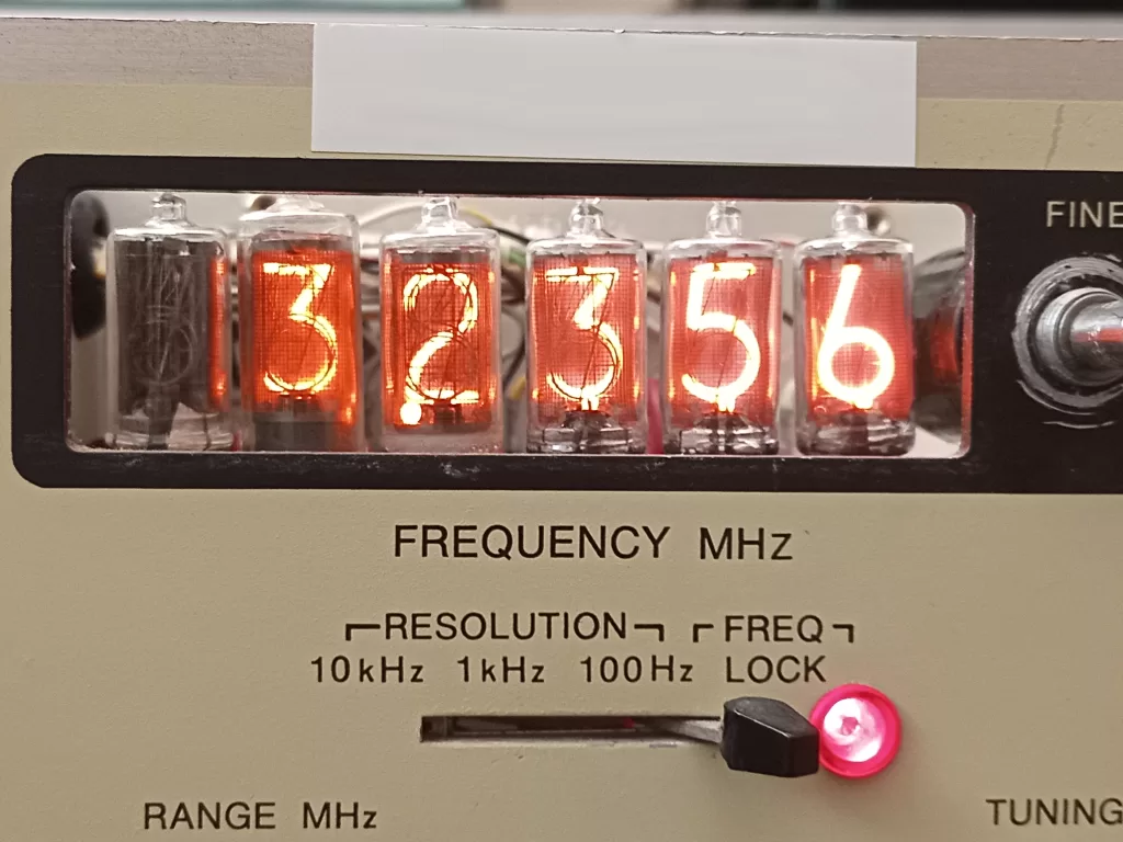
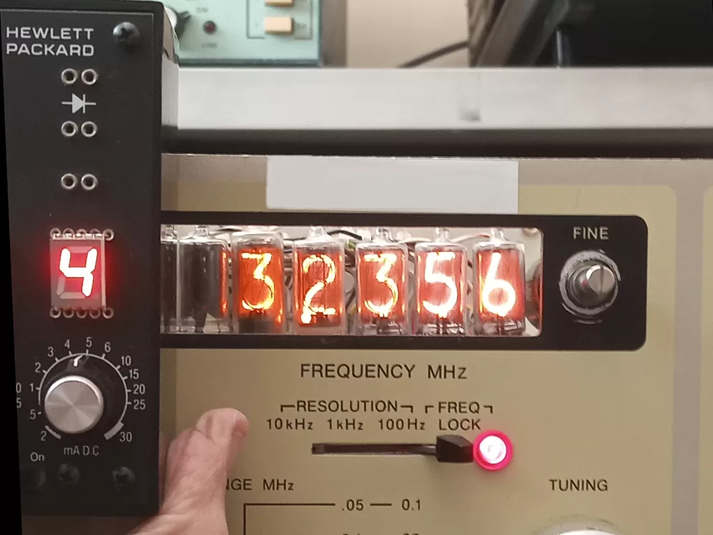
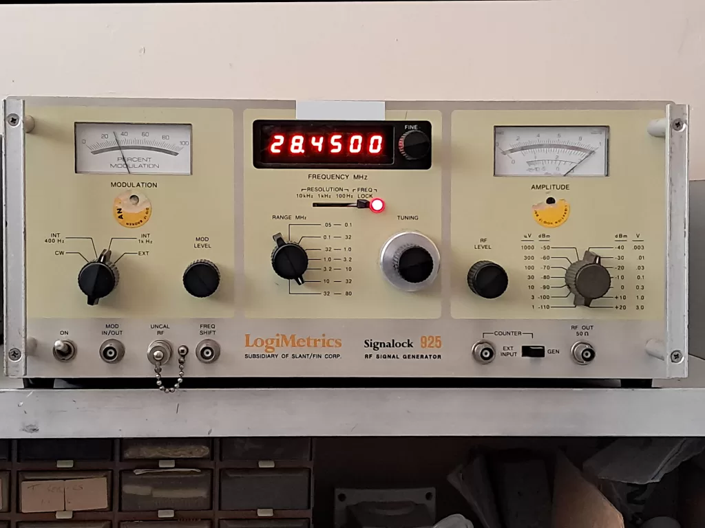
The LogiMetrics 925 is a product of the early 1970’s and sports a nixie1 tube based digital frequency display. While it was possible to determine the value of the missing leading digit, by turning the frequency adjust to minimum and counting the “overflow” value as one adjusted the frequency upwards, it was a slight pain, to put it politely. So nothing for it, let’s give it an overhaul.
The display circutry was quite simple; each nixie tube was driven by a BCD to 1 of 10 decoder IC, so it didn’t take long to determine that we had a faulty nixie tube. Now of couse, nixie tube displays have been essentially superceded and while suitable replacements were available, one could buy a small two-way radio for the pice being asked for one nixie tube. So a display update was in order.
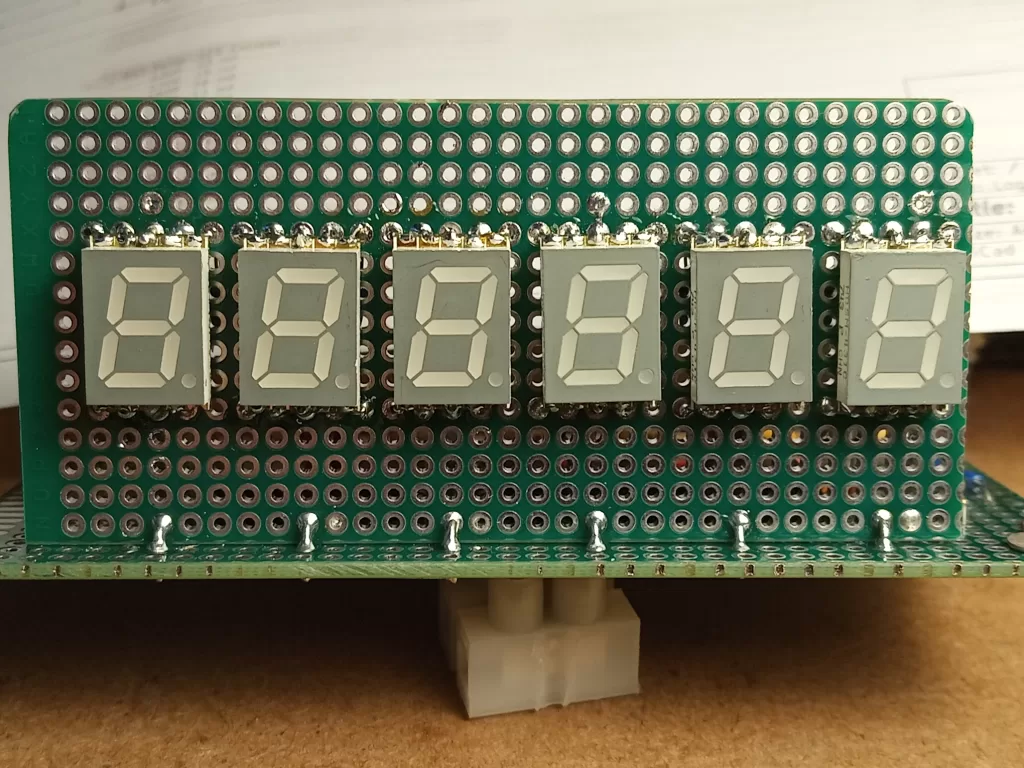
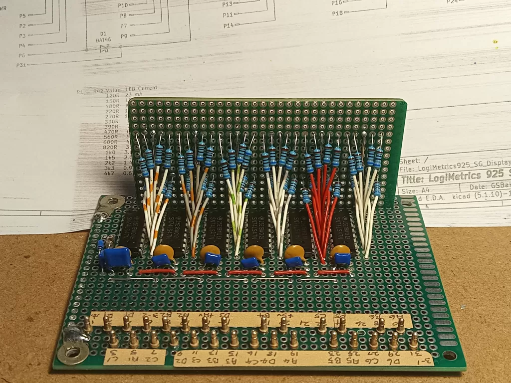
Graham, ZL1TOF volunteered to take on the challenge. The nixie tubes and driver IC were mounted on a separate PCB, so a “drop in replacement” using LED displays was constructed on prototyping perf board.
Firstly a suitable drive current for the LED displays was determined, to provide a comaparatively similiar illumination level. The replacement display was then constructed with interconnects from wirewrap wire and the LED current limiting resistors. The “odd size” terminal posts for the module input wiring were transplanted from the origional nixie PCB.
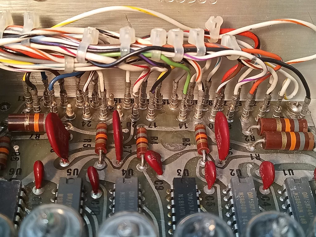
The other issue was the raspy modlation – this turned out to be a degraded connction on a power supply filter cap. Given the generator is over half a century old, I think we can forgive a small possibly age related problem like that.
With a new display, the generator is back to top condition again (nobody mention that the frequency lock unlocks after some time…). The frequency lock unlocking in not really a biggie. The generator uses a free running oscillator and to achieve a frequency lock, one flips a switch to the lock position. This action causes the currently displayed frequency to be stored in memory. This stored value is then continuously compared to the current measured frequency and and difference is represented as a voltage that is used to drive the oscillator back on frequency. As the correction capability has limits, the oscillator can drift further than can be voltage corrected, so the lock light then indicates unlock. One simply then returns the lock control to unlock, manually corrects the frequency then rengages the lock control. Not a biggie, as its quite rare to need a fixed frequency for an extended amount of time.
And now for something completely different… Graham verificating (yes it is a word – I made it up) the seven segment decoding / wiring is all working to plan …
- Nixie: From Dire Straits “Sultans of Swing” – “The band is playing nixie double four time…”
[ED] That’s not even slightly funny; we seriously need a new copy writer ↩︎